Alternator Voltage Regulator Circuit Diagram
The alternator and voltage regulator can both be identified by a triangle symbol that contains either a "+" or "-" sign. When combined, these two symbols indicate the presence of a battery. When installed correctly, the alternator, voltage regulator, and wiring diagram all work together to keep the vehicles electrical system running smoothly.
Delco Alternator Wiring Diagram External Regulator Wiring Diagram
Once you've located the alternator, the rest of the wiring should become clearer. For example, the wires from the alternator will typically connect directly to the battery and the voltage regulator. The last step is to make sure that the voltage regulator is correctly connected in the circuit. This is done by checking the voltage supplied to.

Alternator Voltage Regulation 101 (with Wiring Diagrams) In The
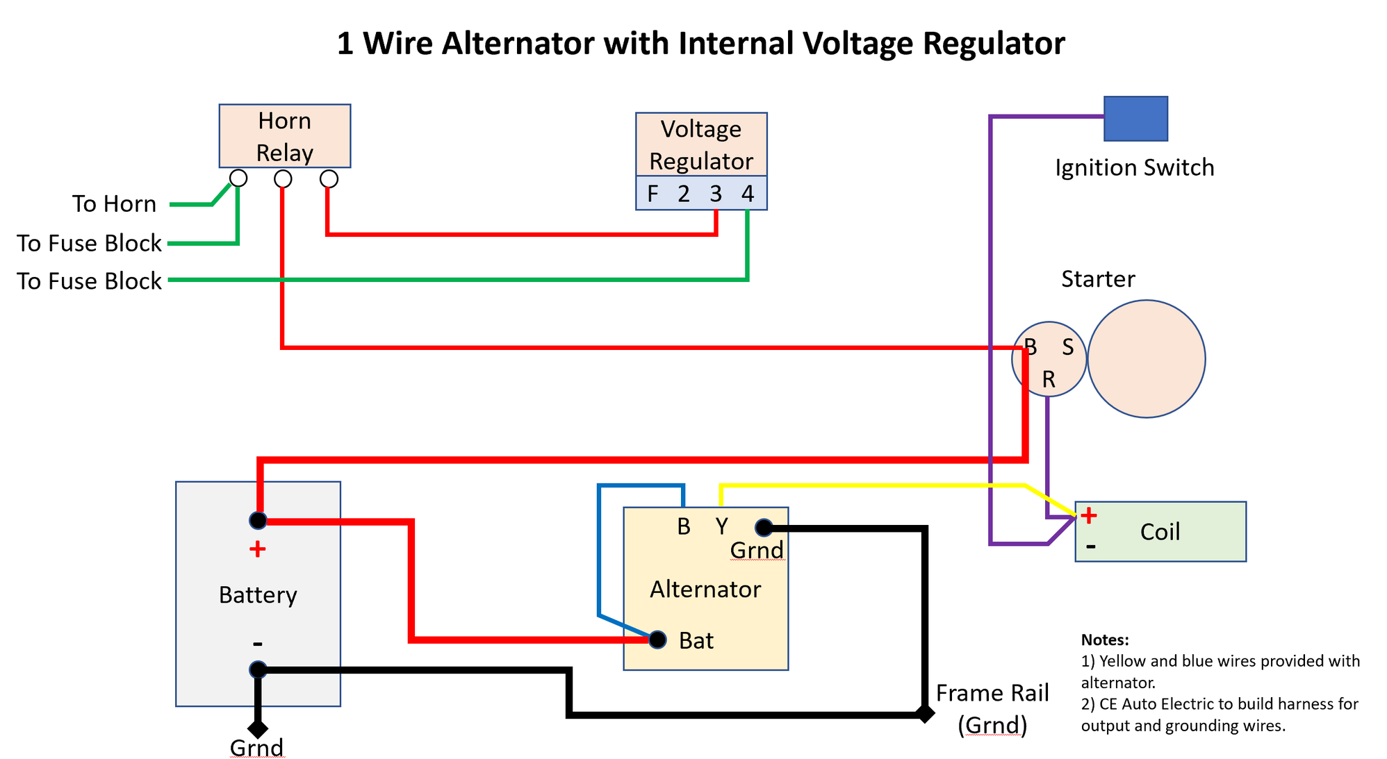
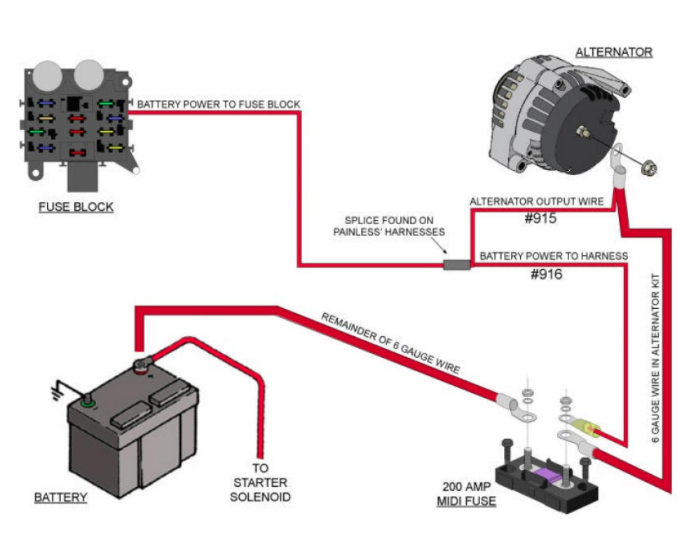
3 Wire Alternator Wiring Diagram. This is a three-wire alternating wiring diagram showing the connections between the different components of a circuit. The circuit comprises three main wires: battery positive cable, voltage sensing wire, and ignition wire. The ignition input wire is attached to the engine.
How to Test Your Alternator's Voltage Regulator AxleAddict
Regulator FET Driver. The CS3361 integral alternator regulator integrated circuit provides the voltage regulation for automotive, 3−phase alternators. It drives an external logic level N channel enhancement power FET for control of the alternator field current. In the event of a charge fault, a lamp output pin is provided to drive an external.

24v alternator wiring diagram Wiring Diagram and Schematic
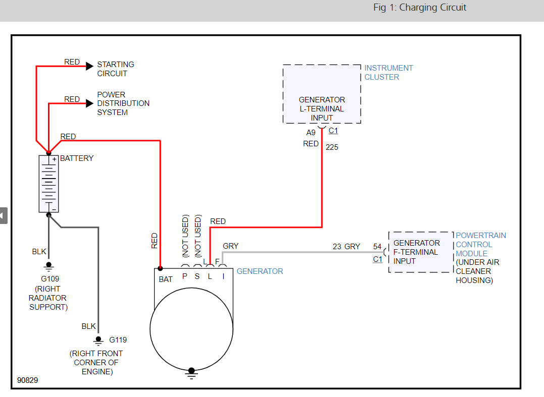
A typical 3-wire alternator wiring diagram with an internal voltage regulator. Computer-Controlled Voltage Regulation. Many late-model vehicles use the engine computer, which is often referred to as the powertrain control module (PCM), to control alternator output. Most modules use an internal driver to turn the alternator's field circuit on.

Car Alternator Voltage Regulator Circuit Diagram
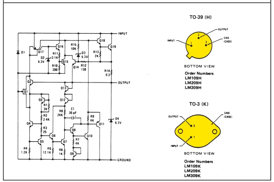
The alternator IC regulator diagram is an electrical circuit that regulates the charging output of an alternator in a vehicle. It plays a crucial role in ensuring the battery is charged properly and that the electrical system of the vehicle operates efficiently. The alternator IC regulator diagram consists of several key components, including.
Alternator Circuit Diagram With Pictures
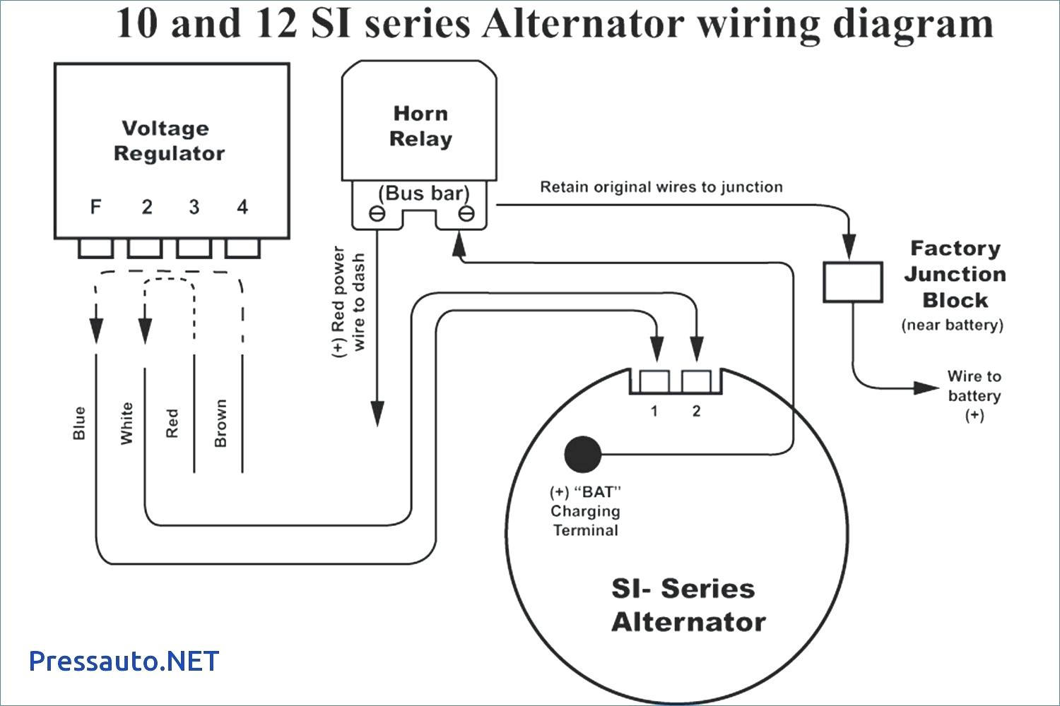
In a 3-wire alternator, the additional fourth wire is for detecting voltage in the ignition system. Some alternators are marked with letters. If the alternator is marked with 'F' (field) and 'R' (reference/sense), then connect 'F' on the alternator to '1' on the regulator, and 'R' to '2'. If you see one marked with 'S.
Voltage Regulator Alternator Wiring Diagram? Is the Voltage
The car alternator voltage regulator circuit diagram is an essential part of any car's electrical system. It regulates electrical output from the alternator, ensuring that the car's battery and other components are receiving the necessary power. Without a well-functioning voltage regulator, the car runs the risk of experiencing electrical problems such as dead batteries and blown fuses.
Car Alternator Regulators
The alternator voltage regulator circuit is a device that regulates the output of the alternator in a vehicle. It ensures that the correct amount of power is being generated by the alternator and that the battery is receiving the correct amount of charge. In most cars, the regulator is located in the center of the alternator and is connected to.
Alternator Wiring Diagram External Regulator
The Alternator Voltage Regulator Circuit is made up of several components, including the alternator, the regulator, the rectifier, and the main fuse. The alternator produces AC current, which is then converted to DC current by the rectifier. The regulator then steps down the voltage, ensuring that the battery is not overcharged.

Circuit Diagram Of Alternator Voltage Regulator Wiring Digital and
Wiring instructions for the early GM Delco Remy external regulated alternator. How to wire an external voltage regulator on a GM vehicle. The early GM alternator is the 10DN series alternator and was used on GM vehicles from about 1963-1970.
Alternator Wiring Diagram With External Regulator Wiring Library
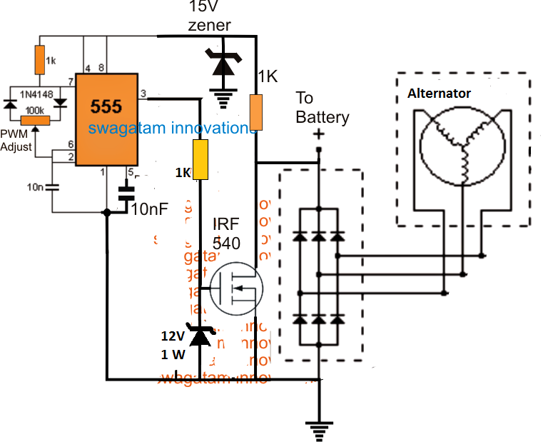
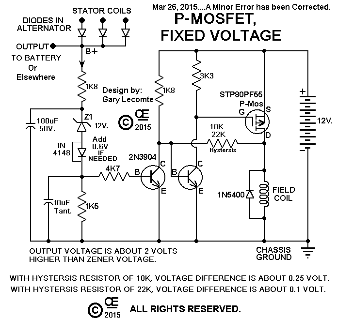
3) Transistorized Car Alternator Regulator Circuit. Referring lo the nest solid-state alternator voltage current regulator diagram below, V4 is configured like a series-pass transistor which regulates the current to the field of the alternator. This transistor along with the two 20 amp diodes are clamped on an external heatsink.
Wiring Diagram For Ford Alternator With Internal Regulator Wiring
Connect the meter's red lead to the battery's positive (+) post and the meter's black lead to the battery's negative (-) post. Notice the open-circuit voltage of the battery. Your battery should be at about 12.6 volts, 12.4 volts minimum; otherwise, charge the battery and continue with this test.
Understanding Voltage Regulation in Power Supply Voltage Regulator
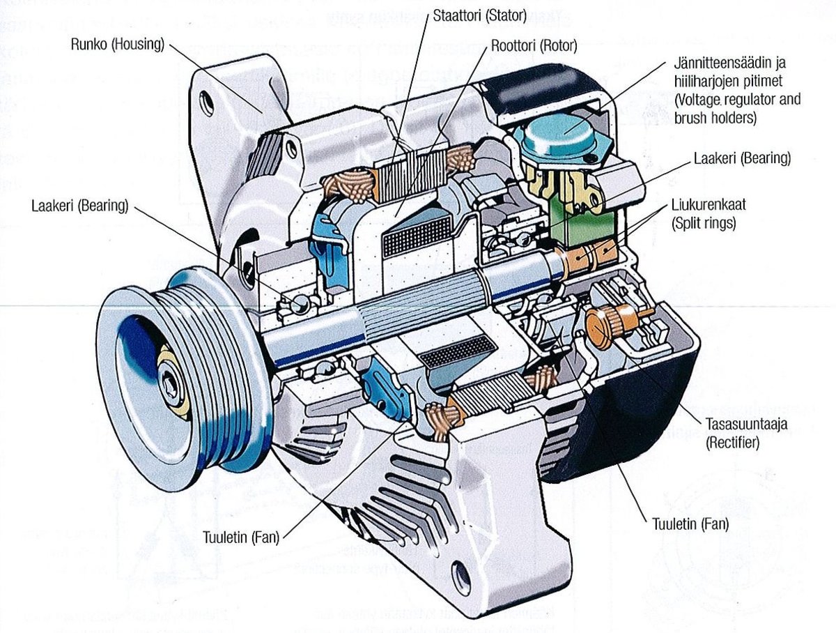
A schematic diagram for an alternator voltage regulator shows the relationship between the main components of the alternator, including the stator coils, rotor magnets, diodes, and the voltage regulator itself.. Alternator Voltage Regulation 101 With Wiring Diagrams In The Garage Carparts Com. Alternator Wiring.
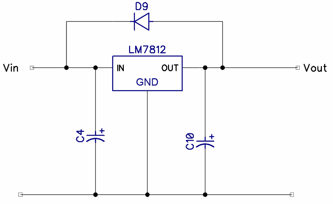
How to Make Voltage Regulator Circuits Circuit Basics
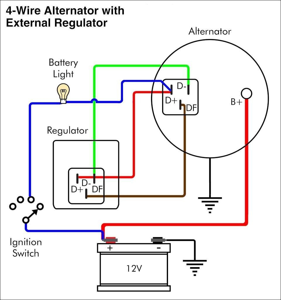
An external regulator alternator is a type of alternator that uses an external voltage regulator to regulate the charging voltage. This is different from an internal regulator alternator, which has the voltage regulator built into the alternator. One key component of the external regulator alternator wiring diagram is the voltage regulator itself.

Ford Voltage Regulator Wiring Diagram Images Wiring Collection
3-Wire Alternator Wiring Diagram, Parts #4: Voltage Regulator. The voltage regulator is a critical component that monitors and controls the electrical output of the alternator. It regulates the voltage and current supplied by the alternator to prevent overcharging of the battery and ensure a stable power supply to the vehicle's electrical system.