
Koleksi 8 Skema Kelistrikan Gl 100 Cdi Grand Gambar Bagaskara
Wiring a CDI and the differance between AC/DC units.
Gambar Skema Cdi Grand Ori Skema Diagram
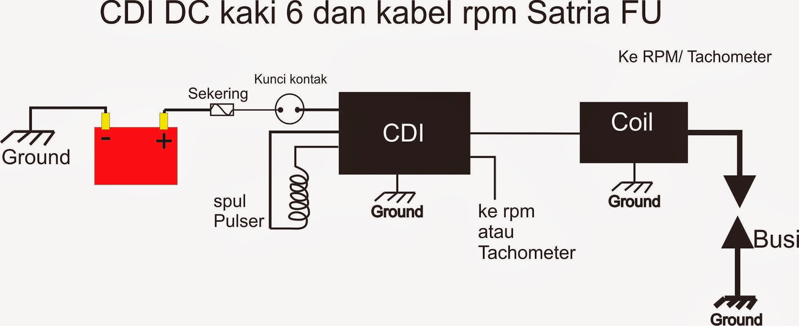
Pada sistem pengapian AC (arus bolak balik) Grand, dilengkapi 5 kabel. Sebenarnya soket CDI pada Honda Grand sangat sederhana. Terdapat lima skema soket CDI Ggrand atau jalur CDI grand, sebagai berikut: Untuk mematikan mesin, kabel dari kunci kontak dihubungkan ke bodi. Artinya saat kunci kontak ON, kabel hitam justru terputus atau tidak.
Gambar Skema Jalur Kabel Cdi Grand Skema Diagram
The 6 Pin CDI comes in the form of a black box fitted with a male connector up top. There are six different electrical pins inside of this connector that serve to provide power to the machine by syncing the various parts of the ignition system. These six pins connect the ignition power to the CDI, the ignition coil, the timing trigger or pulse.
Warna Kabel Cdi Grand kabarmedia.github.io
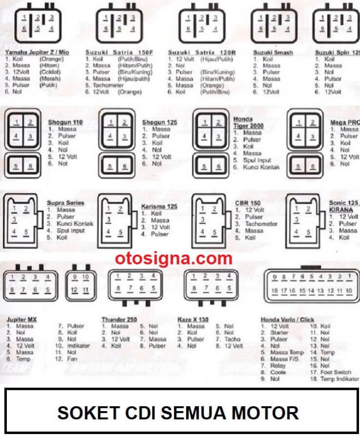
Pada soket CDI pada honda grand atau supra series benar-benar simpel yang hanya memiliki 5 soket atau terminal saja yaitu: Nomor 1 dihubungkan dengan input spul. Soket ini memiliki warna kabel hitam - garis merah. Nomor 2 dihubungkan dengan koil pengapian. Soket ini memiliki warna kabel hitam - garis kuning.

Gambar Skema Cdi Grand Ori Skema Diagram
The wiring diagram for a Chinese 6 pin CDI typically includes six wires: power wire, ignition coil wire, ignition pulse wire, ground wire, kill switch wire, and magneto wire. These wires connect to various components of the ignition system, such as the battery, ignition coil, spark plug, and kill switch. It is important to correctly identify.

6 Pin CDI Wiring Diagram (Illustrated AND Explained!) OffRoad Official
The 5 pins on the CDI connector supply power, ground, and signals to control this process. Here is a quick overview of each pin's function: Pin 1 - Ground. Pin 2 - 12VDC from battery via ignition switch and fuses. Pin 3 - Trigger signal from AC generator stator. Pin 4 - Switched 12VDC to ignition coil.

Yamaha 8 Pin Cdi Wiring Diagrams Everything You Need To Know Moo Wiring
With the right wiring connections, the CDI box controls the ignition timing, spark intensity, and overall engine performance. This comprehensive guide will walk you through the intricacies of the 8-pin CDI box wiring diagram. We'll cover each of the eight pins and their corresponding functions, as well as provide tips for proper installation.

Gambar Skema Cdi Grand Ori Skema Diagram
Soket CDI Grand/Supra Series - Unit CDI jadi salah satunya elemen utama pada sepeda motor terhitung honda grand. Untuk lebih detilnya berikut merupakan ulasan mengenai skema CDI Grand dan soket CDI grand atau supra series. Soket CDI Honda Grand / Supra SeriesPada soket CDI pada honda grand atau supra series benar-benar simpel yang hanya memiliki 5 soket atau terminal saja yaitu:Nomor 1.

Gambar Skema Jalur Kabel Cdi Grand Skema Wiring Diagram
A DC CDI, or Capacitor Discharge Ignition, is a type of ignition system commonly used in motorcycles and other small engine vehicles. It is a high-performance ignition system that provides a strong spark for efficient combustion. To understand the wiring diagram for a DC CDI, it is important to know the different components and connections.

Gambar Skema Cdi Grand No Limit Skema Diagram
Pickup Coil - As the flywheel magnet passes the pickup coil, it generates a small AC voltage. This signal tells the CDI box when to fire the spark plug.; Ignition Coil - Steps up the voltage from the CDI box to the very high levels needed to jump the spark plug gap and ignite the mixture.; Now let's look at the specifics of the 5 pin CDI wiring harness and diagrams.
Gambar Skema Kabel Cdi Grand Skema Diagram
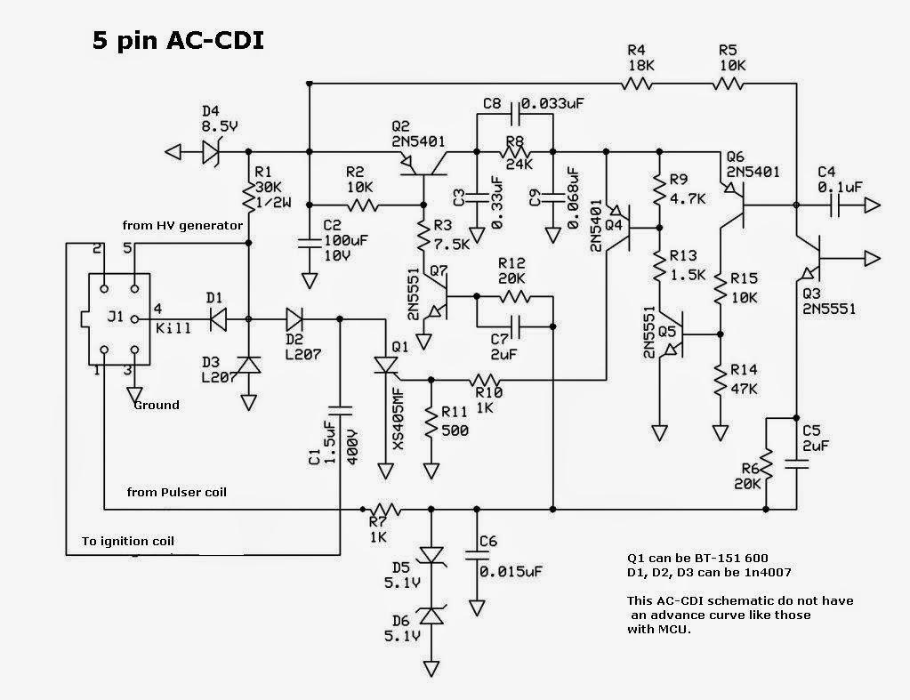
Wiring a CDI involves connecting various wires and components, such as the stator, pickup coil, and ignition coil, in the correct sequence and configuration. This diagram shows you exactly how to wire a 5-pin CDI. Each wire is labeled and color-coded, making it easy to identify and connect the correct wires.

Cdi Ignition Wiring Diagram Herbalic
The 5 wire CDI wiring diagram represents the connection between various components, including the ignition coil, stator, pick-up coil, and the spark plug. Each wire serves a specific purpose and understanding its function is key to diagnosing and resolving any potential issues.

Perbedaan Cdi Grand Dan Supra Extra
#wirings #nonpromechanic #cdiSubscribe for more Vids! Thankyou🙂for sponsorship⤵️⤵️⤵️[email protected](Nonpro Mechanic)

Yamaha Cdi Ignition Wiring Diagram / DCCDI schematic (updated) Techy at day, Blogger at noon
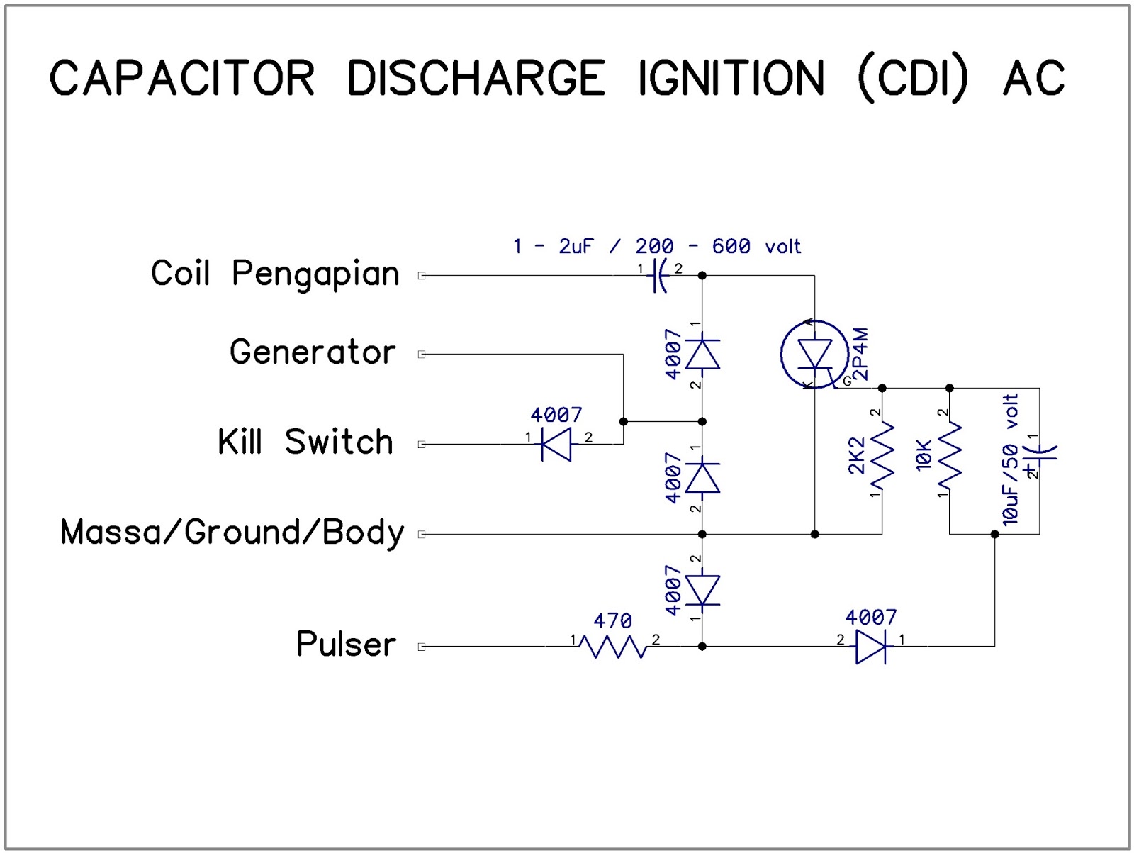
1. Understanding Motorcycle CDI Unit Circuit Diagram. The motorcycle CDI unit circuit diagram consists of an exciter coil, ignition stop switch, diode, capacitor, ignition coil, resistor, gate, and trigger. The system's main purpose is to create the spark, which ignites an air mixture within the motorcycle engine.
Gambar Skema Cdi Grand Ori Skema Diagram
Install the new Switchbox on the mounting plate using the bolts removed previously. Make sure the ground wire connected to a clean ground point. Tighten the mounting plate for the Switchbox and the Ignition coils back up. Connect the Brown/Blue wire labeled #1 and the Brown/Yellow wire labeled #2 to the #1 Switchbox.

5 Wire Cdi Box Wiring Diagram
The 5 Pin CDI Box. The 5 Pin CDI comes in the form of a black box, fitted with a male connector at the top. Inside of this male connector, there are five different pins that connect to the various parts of the ignition system to provide power to the machine. These five pins connect the timing trigger/pulse generator, ignition coil, ignition.